Ozone is a strong oxidant that can remove color and odor from water, reduce the permanganate index, and oxidize and degrade difficult-to-degrade high molecular organic matter. At the same time, it has disinfection and sterilization effects. When the quality of effluent water is relatively high or when there are difficult-to-degrade organics in the raw water, ozone oxidation and its combined processes have good treatment effects. On the other hand, compared with traditional urban sewage treatment
In summary, the compliance and rationality of ozone oxidation and its combined process design directly affect the treatment effect, project investment, operating costs, and production safety. Therefore, this paper summarizes the key points and easily overlooked issues in the design of ozone treatment systems, and conducts an exploration and analysis to provide reference for similar projects.
1 Key points of gas source system design
1.1 Selection of gas source system
Industrial ozone is formed by high-voltage discharge of oxygen. The gas source supplied to the ozone generator can be air (CDA) or pure oxygen. Pure oxygen can be prepared on site (V-GOX) or purchased as liquid oxygen (LOX) through evaporation. Different gas sources result in significant differences in the cost of supporting systems, raw material costs, operating costs, and maintenance workload for ozone generators. Assuming that the conditions for purchasing and transporting liquid oxygen are allowed, using air as the gas source for ozone generators becomes economical when the ozone generation capacity >60kg/h; when the total ozone system preparation capacity in engineering applications is ≤60kg/h, using liquid oxygen as the gas source for ozone generation is more economical. For typical indicators of different gas sources, CDA source ozone generators generally consume electricity at a rate of 15~25kW·h/kgO, resulting in an ozone concentration of about 1%~2%; LOX source ozone generators generally consume electricity at a rate of 8~10kW·h/kgO3, resulting in an ozone concentration of about 6%~10%, and when the generator economy is very good, the ozone concentration is around 10%; V-GOX source ozone generators generally consume electricity at a rate of 8~10kW·h/kg03, resulting in an ozone concentration of about 6%~10%.
1.2 Key Design Points of Air Source System
The air source system mainly consists of air compressors, rear coolers, buffer tanks, filters, dryers, pressure stabilizing gas storage tanks, pipeline valves, supporting instruments, etc. The requirements for the use of compressed air in ozone generators are as follows: the particle size of dust is 1um, the maximum concentration is 1ug/L, the maximum pressure dew point is -40℃, and the maximum oil concentration is 1ug/L.
1.3 Key Design Points of Liquid Oxygen Source System
The liquid oxygen source system generally consists of liquid oxygen storage tanks, remote level monitoring systems for storage tanks, liquid oxygen vaporization systems, pressure regulating valve assemblies, filtration equipment, etc.
Liquid oxygen storage tanks are usually leased and the design, installation, commissioning, and operation and maintenance are carried out by professional gas source suppliers. However, attention should still be paid to the following aspects:
① The liquid oxygen transfer tanker is a large truck. Generally, the road width near the liquid oxygen station should not be less than 6m, and the turning radius should not be less than 14m;
② The typical floor area of a liquid oxygen station is 5m×10m;
③ The storage capacity of liquid oxygen tanks is generally 3~5 days' consumption. The purity of oxygen is generally 99.5%~99.9%, and the particle size of impurities is <0.1um;
④ The liquid oxygen vaporization system should generally consider setting up one for use and one for standby. In addition, for northern regions, the evaporation capacity at low environmental temperatures should be considered. Electric heating load and devices should be reserved in the design [3];
⑤ The gauge pressure after the pressure regulating valve assembly is generally 0.3MPa;
⑥ A dew point instrument should be set up after the pressure regulating valve assembly. The normal pressure dew point of oxygen is -65℃, which will affect the uniformity of the generator discharge;
⑦ The oxygen delivery pipeline should adopt GC3 grade stainless steel pressure pipeline. The connection method should be welding. Before welding, pickling passivation, cleaning, and degreasing treatments should be carried out [4];
⑧ When the working pressure of the oxygen delivery pipeline is 0.1~1MPa, the maximum allowable flow velocity under working pressure is 30m/s. The design flow velocity is generally taken as 10m/s;
⑨ The main oxygen delivery pipe should be laid in the pipe trench. In cold areas, insulation measures should be considered. The pipe trench should be as straight as possible and avoid major traffic roads;
⑩ The minimum distance between oxygen pipelines, pipe racks, roads, and buildings (structures) should meet the requirements of specifications.
1.4 Key Design Points for On-site Oxygen Production System
The methods for on-site oxygen production mainly include cryogenic distillation and adsorption separation. Cryogenic distillation consumes approximately 260~340kW·h of electricity per ton of oxygen produced, with the purity of the oxygen output exceeding 99.5%. This method has a higher investment cost but lower operating costs, and is mainly suitable for situations with high oxygen consumption and high purity requirements. Adsorption separation consumes approximately 0.2~0.3kW·h of electricity per Nm3 of oxygen produced, with the purity of the oxygen output being around 90%~93%. Due to the need for regular shutdown maintenance of on-site oxygen production equipment, it is necessary to equip it with a certain capacity of liquid oxygen storage tanks and their evaporative gas supply devices that meet the requirements for shutdown gas supply. There are relatively few engineering application cases for this method of oxygen production.
The on-site oxygen production system generally requires a pure oxygen content of ≥90%, a normal pressure dew point of ≤-60°C, impurity size <0.1um, and a gas supply pressure of ≥0.2MPa.
2 Key Design Points for Ozone Preparation and Ozone Generator Cooling System
2.1 Key Design Points for Ozone Preparation System
The core parameter of ozone equipment is the ozone dosage, which is determined based on different purposes and usually does not have a standby machine. Typically, when used for decolorization, the ozone dosage is 2.5~5mg/L; when used for COD degradation, the ratio of COD removal to ozone dosage is generally 1:2~1:4; when used for disinfection of sewage plant tailwater, the ozone dosage is 5~15mg/L.
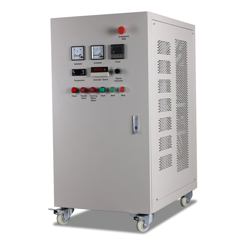
The core components of the ozone generator are high-frequency current type frequency converter and discharge tubes. During the equipment selection stage, the following points should be noted:
① Each discharge tube should have an independent fuse to prevent the entire ozone generator from shutting down due to a fault in one discharge pipe, affecting production;
② The discharge gap of the discharge tube is generally 0.3~0.5mm. The smaller the discharge gap, the less heat generated, the easier it is to cool, and the higher the efficiency;
③ The service life of the discharge device of imported ozone generators should guarantee at least 10 years, and the overall quality assurance period of the generator is 2 years, during which the failure rate of the discharge tubes should not exceed 0.1%;
④ Guarantees should be provided for ozone concentration and output, which should be measured during acceptance, and the output should be adjustable within 10%~100%.
For oxygen source ozone generators, in order to improve their discharge yield and protect the discharge tubes, nitrogen gas is usually added to pure oxygen at a rate of 1%~3% (mass fraction), known as the "nitrogen supplement" system. The nitrogen supplement system is mainly composed of oil-free air compressors, refrigerated dryers, dryers, etc., and is provided by ozone generator manufacturers as a complete set.
Pipelines in the ozone generator room should be laid in trenches or considered overhead installation. No matter what installation form is adopted, it should meet relevant specifications and leave space for maintenance access.
2.2 Design Key Points of Ozone Generator Cooling System
High temperatures are not conducive to the production of ozone and can accelerate its decomposition, leading to a decrease in ozone concentration and yield. The cooling water is mainly used to exchange the heat released by the discharge tube of the ozone generator. The higher the temperature of the cooling water, the greater the power consumption of the ozone system. The cooling water system is divided into two types: closed-loop circulation and open-loop circulation. Among them, open-loop circulation has a high requirement for water quality, generally requiring a certain level of chloride ion content, and is suitable for small generators. In closed-loop circulation, the internal cooling water is mainly used to cool the discharge tube and should be high-purity deionized water (conductivity of 5uS/cm); the external cooling water cools pure water through plate heat exchangers, so it has low requirements for cooling water quality [3], and is suitable for large generators. For urban sewage treatment plants that mainly treat domestic sewage, when the effluent quality meets the Grade A or higher standards in the "Discharge Standards of Pollutants from Urban Sewage Treatment Plants" (GB18918-2002), the treated wastewater can be used as the source of external circulation cooling water (when the water temperature > 35°C, additional cooling facilities such as cooling towers need to be considered). The flow rates of internal and external circulation pumps vary due to different air sources of the generator.
For closed-loop cooling systems, the material of plate heat exchangers and their supporting pipe fittings should be SS304 or above; during the selection process of plate heat exchangers, attention should also be paid to whether the parameters such as heat transfer coefficient, heat exchange area, working pressure, working temperature, processing capacity, and chevron angle meet actual needs. Generally, the head loss of plate heat exchangers is about 20~50kPa.
Design Key Points for Ozone Dosing and Contact Reaction System
1.3.1 Design Key Points for Ozone Dosing System
In actual working conditions, the design flow rate of the main pipe for ozone dosing is generally 10-15m/s. It is worth noting that the mixed gas pressure of ozone and oxygen at the outlet of the ozone generator is usually 0.1MPa, and the temperature is generally 20-30℃ (related to air temperature, cooling water temperature, generator working conditions, etc.). When calculating the pipe diameter under actual working conditions, the volume flow rate of the mixed gas under standard conditions should be converted into the volume flow rate of the mixed gas under actual working conditions according to Boyle's Law, and then the pipe diameter for ozone dosing can be calculated using Darcy's formula.
The materials of pipes, fittings, and valves should be SS316L with a design working pressure of 0.1MPa, which belongs to GC2 pressure pipeline[]; when the chloride ion content in raw sewage is high, the material of the branch pipe for ozone dosing in the ozone contact tank should consider using duplex steel or other materials with high chloride ion concentration resistance. The seals of the ozone dosing system should be made of PIFE (polytetrafluoroethylene), PVDF (polyvinylidene fluoride), perfluoro rubber, or other ozone-resistant materials. The connection of ozone pipes should be welded, and before welding, the stainless steel pipes should be pickled, passivated, cleaned, and degreased[]. After welding, non-destructive testing should be performed on the weld seam at a rate of 10% to meet the acceptance standards.
The main pipe for ozone dosing should be laid in a pipe trench with a removable cover plate. For areas with hot climates, the exposed part of the pipe should be insulated according to relevant specifications, and insulation materials such as PUR (polyurethane) can be used. The thickness of the insulation layer should be determined through calculation and is generally 25mm.
3.2 Design Key Points for Ozone Contact Reaction System
The contact time between ozone and wastewater varies depending on the type of pollutants to be removed by ozone. For decolorization, the contact time is 10-20 minutes; for COD degradation, the contact time is 15-60 minutes (with 3-6 air distribution zones, each with an contact time of 8-15 minutes); for disinfection, the contact time is 6-15 minutes, or after a contact time of 3-5 minutes, it should be retained for 10-15 minutes. The design of ozone contact pool compartmentation, classification (number of sections), ozone dosing ratio per section, tail gas destruction, etc., should all follow relevant specifications; vertical partition walls should have connecting holes at the lower part (for easy drainage) and pressure balance holes at the upper part.
In addition, the key points for the design of ozone contact pool are as follows:
① A flow path that surpasses the contact pool should be considered and preferably implemented within the pool body [8];
② Each compartment of the contact pool should have an independent venting system for easy maintenance [9];
③ The last reaction zone of the contact pool and the water outlet well should undergo two bends (i.e., an additional buffer chamber) to completely isolate the ozone reaction system from downstream process facilities [4];
④ The internal sleeve of the ozone contact pool should be made of SS316L material; the outlet pipeline should also be made of SS316L, and after a certain distance, it should be connected to carbon steel pipes using insulating flanges [10-1];
⑤ Online monitoring of gas phase ozone concentration is best done using a UV absorbance meter, while online monitoring of residual ozone concentration in water should use a diaphragm electrode instrument [2].
Ozone contact pools in sewage treatment plants are recommended to use microporous diffusion disks to release ozone. The disk material should be ceramic or titanium alloy + SS316L stainless steel, with a diameter of 120mm or 150mm. The service area per disk is generally 0.6-1m2, and the throughput of a single aeration disk is typically 1.5-2Nm3/h. The head loss of the diffusion disk is generally 5-6kPa. The inlet and outlet gates, vent valves, and pipe fittings inside the contact pool should all be made of SS316L.


